Editor's note: This is a chapter excerpt from "Designing and Deploying 802.11 Wireless Networks," by Jim Geier and published by Cisco Press.
It is possible to configure WLANs into different architectures, depending on the requirements of the system. The physical architectures include the following:
■ Ad hoc
■ Infrastructure
■ Mesh
Ad hoc wireless LANs
Ad hoc WLANs (sometimes referred to as “peer-to-peer” WLANs), as shown in Figure 3-1 , only require 802.11 client radios in the client devices that connect to the network. Because there is no access point or WLAN controller and the stations are within range of each other, data transmitted by a particular source station travels directly to the applicable destination station. The rationale behind the ad hoc form of networking is to enable users to spontaneously set up WLANs. Access points are not necessary, which makes peer-to-peer networks easy to set up and take down. This can be beneficial, for example, if you want to establish a WLAN among several laptops in a conference room for a meeting in a building that has no WLAN that the laptops can connect to. These networks require no administration and very little preconfiguration. All that’s needed to set up an ad hoc WLAN is to set the 802.11 radio in Microsoft Windows-based client devices to ad hoc mode.
The ad hoc form of communications is especially useful in public-safety and search-andrescue applications. Medical teams require fast, effective communications when they rush to a disaster to treat victims. They cannot afford the time to run cabling and install networking hardware. The medical team can use 802.11-equipped laptops and enable broadband wireless data communications as soon as they arrive on the scene.
The absence of an access point in an ad hoc network means that an ad hoc WLAN must take on more of the MAC-layer responsibilities. The first active ad hoc station (802.11-equipped client device set to ad hoc mode) establishes an IBSS and starts sending beacon frames, which are needed to announce the presence of the ad hoc network and maintain synchronization among the stations. Other ad hoc stations can join the network after receiving a beacon and accepting the IBSS parameters (for example, beacon interval) found in the beacon frame.
Each station that joins the ad hoc network must send a beacon periodically if it does not hear a beacon from another station within a short random delay period after the beacon is supposed to be sent. The random delay minimizes the transmission of beacons from multiple stations by effectively reducing the number of stations that will send a beacon. If a station does not hear a beacon within the random delay period, the station assumes that no other stations are active, and a beacon needs to be sent. After receiving a beacon, each station updates its local internal clock with the timestamp found in the beacon frame, assuming that the timestamp value is greater than the local clock. This ensures that all stations can perform operations, such as beacon transmissions and power management functions, at the same time.
Infrastructure wireless LANs
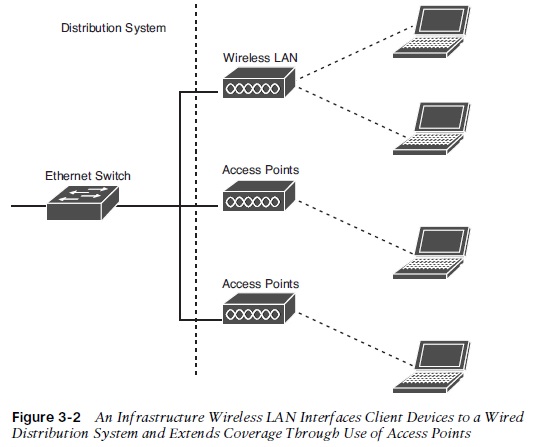
Most companies, public hotspots, and homeowners implement infrastructure WLANs. An infrastructure WLAN, as shown in Figure 3-2 , offers a means to extend a wired network. In this configuration, one or more access points interface wireless mobile devices to the distribution system. Each access point forms a radio cell, also called a basic service set (BSS), which enables wireless users located within the cell to connect to the access point. This allows users to communicate with other wireless users, as well as with servers and network applications connecting to the distribution system. A company, for example, can use this configuration to enable employees to access corporate applications and the Internet from anywhere within the facility.
Each access point in the infrastructure WLAN broadcasts beacon frames, which identify the presence of the WLAN and synchronizes various events, such as 802.11 power management. Each access point creates a radio cell, with a coverage area that depends on the construction of the facility, chosen PHY layer, transmit power, and antenna type. This range is typically 100 feet in most enterprise facilities, depending on the data rate and environmental factors, such as building construction.
The desired level of performance, however, can impact the effective range of the access points. Lower data rates offer longer range than do higher data rates.
If a company installs access points with overlapping radio cells, as shown in Figure 3-3 , then users can roam throughout the facility without any noticeable loss of connectivity.The radio card within the user’s mobile device will automatically re-associate with access points having stronger signals. For example, a user might begin downloading a file when associated with access point A. As the user walks out of range of access point A and within range of access point B, the client radio automatically re-associates the user to access point B and continues the downloading of the file through access point B. The user generally does not experience any noticeable delays, but voice over WLAN phones might drop connections if the roaming delay exceeds 150 milliseconds.
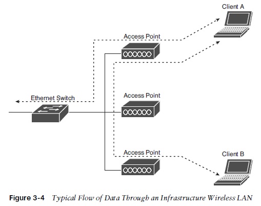
In infrastructure WLANs, data transmissions do not occur directly between the wireless clients. Data traffic going from one wireless user to another user must travel through an access point (see Figure 3-4 ). The access point receives the data traffic going from client A to client B, for example, and retransmits the data to client B. As a result, significant data traffic between wireless users decreases throughput because of the access point needing to relay the data to the destination user. If the source wireless user is sending data to a node on the distribution system, then the access point does not need to retransmit the data to other wireless users. The access point (if it is an autonomous type) delivers the data directly to the distribution system for routing to the applicable node. In the case of a controller-based WLAN, the access point hands over the data to an applicable controller, and the controller delivers the data to the distribution system.
In addition to overlapping cells, the 802.11 standard also supports collocated and disjointed radio cells, as shown in Figure 3-5 .
The collocated radio cell configuration is useful if a company needs greater capacity than a single access point can deliver. In this scenario, two or more access points are set up so that their radio cells overlap significantly. This works well if the access points are set to non-conflicting radio channels. A portion of the users in the area, for example, associate with access point A, and the other users associate with access point B. This boosts the capacity of that particular area.
A company can install disjointed access points when complete coverage throughout the facility is not necessary. For example, the company might install an access point in each conference room and not the rest of the building. If the radio cells are disjointed, then users will temporarily lose connection to the network and then re-associate when they come within range of another access point. An 802.11 network, though, supports this form of network, similarly to roaming with the overlapping radio cells. The re-association delay is a function of the time it takes the user to move into range of the next access point. The wireless application in use, however, might or might not be able to tolerate this longer roaming delay.
Wireless mesh networks
Wireless mesh networks make use of mesh nodes, which are similar to access points, except that mesh nodes connect to each other wirelessly rather than via Ethernet, as do most infrastructure wireless networks (see Figure 3-6 ). Thus, mesh networks avoid the need for Ethernet connections. You can install them just about anywhere, as long as electrical power is available (or you can use solar power for most outdoor installations).
A mesh network is beneficial in areas where it is not feasible to install a traditional WLAN consisting of access points. For example, a mesh network approach makes sense in residential and city-wide Wi-Fi networks. The deployment of cabled access points over larger, open areas is a daunting task because of the massive amount of data cabling that must be installed and the countless permissions. Other places where installations of cabled access points are difficult include convention centers, college campuses, stadiums, marinas, parks, and construction sites.
Client devices connect to a mesh node similar to the method used for connection to an access point in an infrastructure network. Each mesh node implements a routing protocol that routes packets between client devices and wired connections to the Internet and servers. A mesh network offers multiple paths from source to destination, and intelligent routing algorithms allow each node to make a decision on which path to forward packets through the network to improve performance. If the link between a pair of nodes along one of the paths is congested, for example, then the algorithms establish another path that avoids the congested link. Also, if a node goes down, an alternate route is chosen based on the routing algorithms.
Latency can vary significantly on mesh networks, depending on the number of users and hops that are necessary for moving packets through the backhaul network. Roaming and routing delays can affect performance, especially for VoIP applications. Even if the data rate between the user and the local backhaul node is kept high, which many of the mesh network vendors claim, the delays across the network might be substantial.
Often the lack of electrical power for mesh nodes in some areas leads to installation delays and unforeseen costs. In outdoor installations, some light poles do not supply adequate electrical power, or occasionally mounting assets, such as rooftops, do not have any readily available power. In these cases, the use of solar panels can be an option for generating power for mesh nodes and backhaul equipment. In this case, the network equipment actually runs off a battery, and the solar panel generates electricity to recharge the battery and power the mesh node if the battery is charged. Without a battery, there would be no power available at night or when something, such as clouds, obstructs the sunlight.
The use of solar energy is free, which can save electricity costs when running a mesh network. A problem, however, is that the cost of solar panels and batteries can be several hundred dollars for each mesh node. This makes the use of solar power generally feasible only where the cost of installing electrical lines is relatively expensive or where electricity is very unreliable. For example, Chittagong in Bangladesh decided to power some mesh nodes with solar energy because electrical power there is not stable enough.
If using solar panels for generating electricity for mesh nodes is appealing, then be certain to investigate average sunlight on a daily basis and ensure that the solar panels and batteries specified will supply an adequate amount of power for the equipment. This can be a bit tricky because predicting the amount of sunlight might not be accurate enough to satisfy network availability requirements.


