Network Computing is part of the Informa Tech Division of Informa PLC

This site is operated by a business or businesses owned by Informa PLC and all copyright resides with them. Informa PLC's registered office is 5 Howick Place, London SW1P 1WG. Registered in England and Wales. Number 8860726.

Cable Management: Tackling Tangles

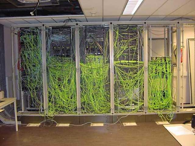
  • Historically, intermediate distribution frames  in wired Ethernet environments -- the racks filled with telecommunications cable -- pose an operational challenge, as the staff involvement required for moves/adds/changes (MAC) increases across time as the complexity of the cable tangle increases. 

    Moreover, tangled cable increases mean time to repair (MTTR) when components in Ethernet switches fail. As a result, a  process that can take minutes early in the life of the IDF can become an ordeal requiring hours or even days after an IDF has been in operation for years. Similarly, cable tangle increases the labor and downtime costs of equipment upgrades. On the following pages, I examine cable management approaches that keep MAC, MTTR, and upgrade costs constant across time.

    Stuart Kendrick is a Systems Engineer at the Allen Institute in Seattle, WA USA. He has been supporting operational IT environments since 1985, teaches at LISA, SharkFest, and CasitConf, and specializes in monitoring and troubleshooting.

  • The problem

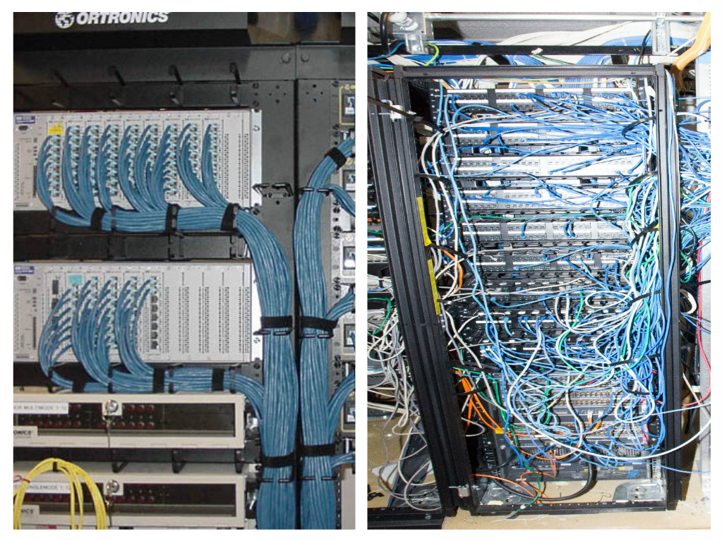
    Typically, the cost of moves/adds/changes in intermediate distribution frames increases over time, as the original installation starts off organized (left-hand panel) and, when exposed to MAC, heads toward cabling chaos (right-hand panel).

    Not only does the cost of staff time for MAC work increase, but the cost of electronics replacement increases -- replacing a failed power supply, fan, or line card, much less an entire chassis, becomes a challenging multi-hour process in small deployments. In dense deployments, equipment replacement becomes cost prohibitive:  Replacing a component can become a multi-day affair, as the cable tangle must be painstakingly documented and removed before component replacement can even begin: an IDF burn-down. 

    Oftentimes, cable restoration results in further downtime for specific end-stations, as the documentation process generally misses some cross-connects.  In particularly tangled installations, even MAC work can result in collateral service disruption, as the process of installing/removing/shuffling a cable can detach neighboring cables.

    Costs that increase over time:

    • Staff time for MAC work
    • Staff time for equipment repair
    • Staff time for equipment replacement


    Service disruption that increases over time:

    • MTTR for electronics failure
    • Downtime during equipment upgrades
    • Collateral service disruption after MAC or equipment replacement
  • Cable choices

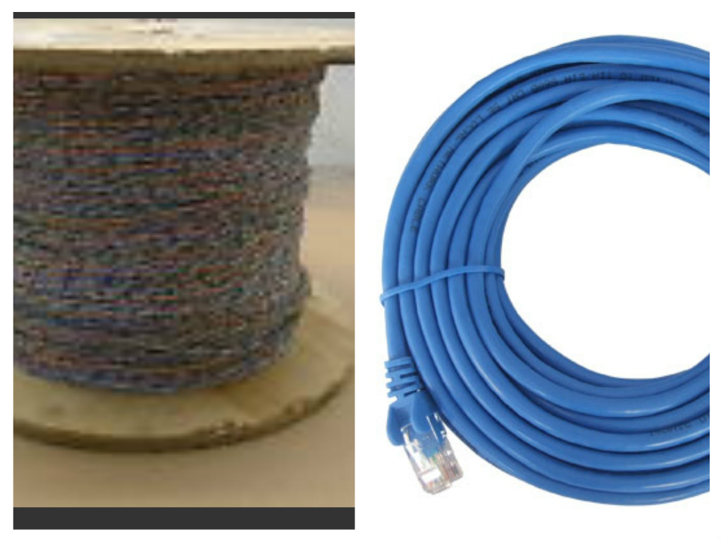
    The telecom world has recognized these cable management problems and dealt with them by using bare cross-connect wire (left-hand panel), thus dispensing with the plastic sheath and RJ-45 connectors of the patch cord (right-hand panel). Doing this shrinks volume by 30% and weight by 50%.

    Additionally, installers cut bare cross-connect wire in situ to precisely the correct length, further shrinking volume, weight, and cable clutter. Finally, bare cross-connect wire's coefficient of friction is low, substantially lower than that of the plastic-encased patch cords. Reduced friction facilitates the tracing and removal of defunct cross-connects. Retiring defunct cross-connects is essential to keeping cable density constant across time.  By contrast, IDFs in which defunct cross-connects accumulate enter a downward spiral, as density and clutter increases and the cost of retiring defunct cables similarly increases.

    While there isn't standard terminology for cable management designs, we in the Pacific Northwest use some common references. IDFs that use bare cross-connect wire terminated on blocks are called punch-punch designs, while IDFs employing patch cords are called patch-patch designs. Variations of punch-punch designs include rack-punch and wall-punch. The actual origin of these terms is unknown, but the designs have proven successful.

  • Wall-punch design

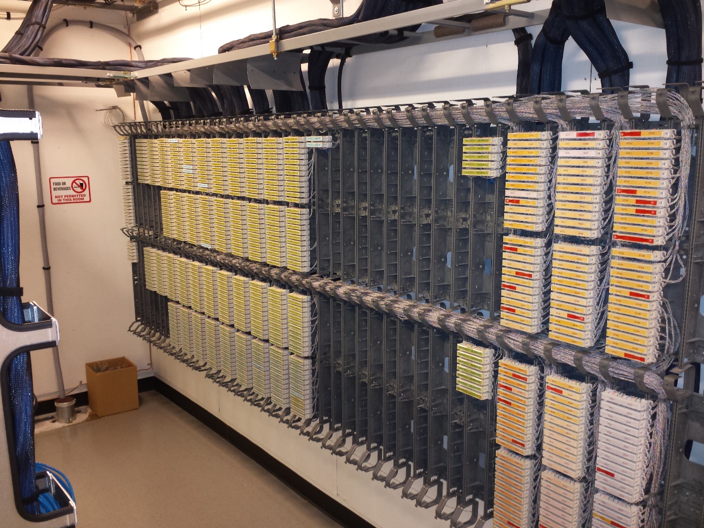
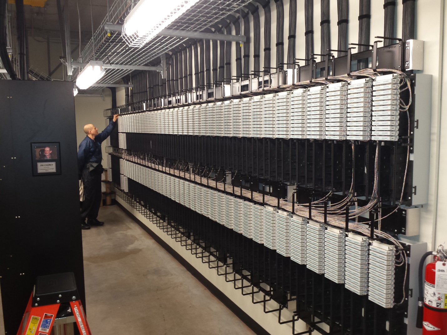
    In a wall punch design, both station cables and Ethernet switch ports are terminated on blocks mounted on the walls of the IDF, with cross-connect wire running between the two along cable management pathways installed above, below, and in the middle of the block fields. This installation employs ADC Ultim8 blocks.

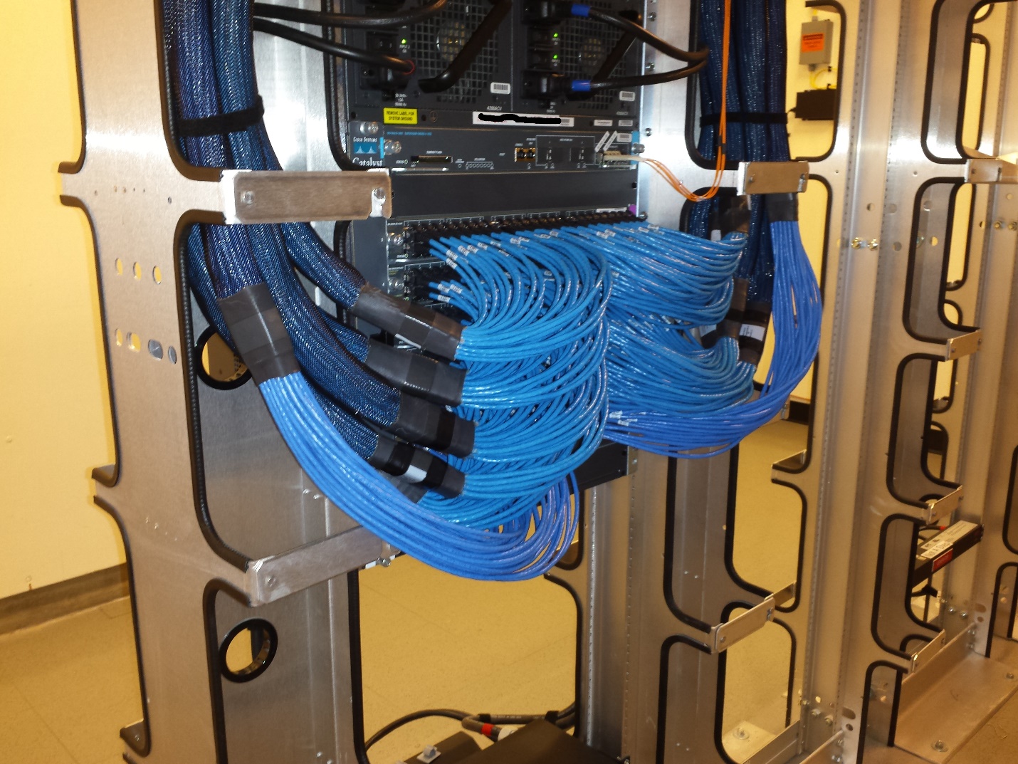
    In the photograph above, the station cabling appears on the left side of the block field, while Ethernet ports are featured out on the right side. The Ethernet switch, or rather its associated switch harnesses, are barely visible (blue cable) on the extreme left-hand side of the photograph.

    This IDF has been in operation for a dozen years and has been exposed to steady churn, in which techs retire defunct cross-connects and later install new ones as offices are emptied, reconfigured, and reoccupied. At no point have we performed an IDF burn-down.

  • Switch harnesses

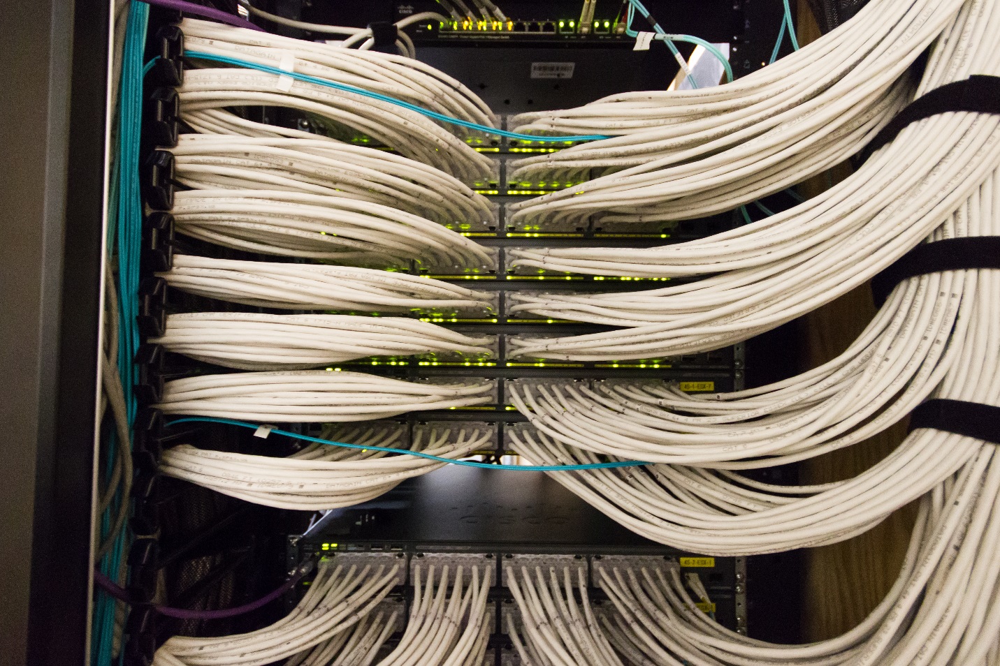
    Here we focus on the Ethernet switch and its switch harnesses:  the portion of the picture barely visible in the previous photograph.  Typically, the switch harnesses are factory-made, shipped to the site, and installed by professional cable technicians.

  • Data center deployment

    The same scheme can be applied to data centers. Pictured here is the cross-connect room of an 800 KW data center, terminating ~3500 cables and ~500 cross-connects. This room has been in operation for five years.

  • Rack-punch design

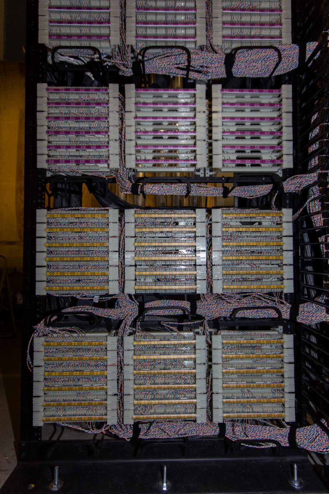
    Alternatively, in the rack-punch design, blocks are mounted in racks in the middle of the IDF, again with cross-connect wire traversing cable management pathways installed between each row of panels. This installation employs Ortronics 110 blocks.

  • Panel view

    Here we approach a single panel for a detailed view of the rack-punch design.

  • Station-labeling

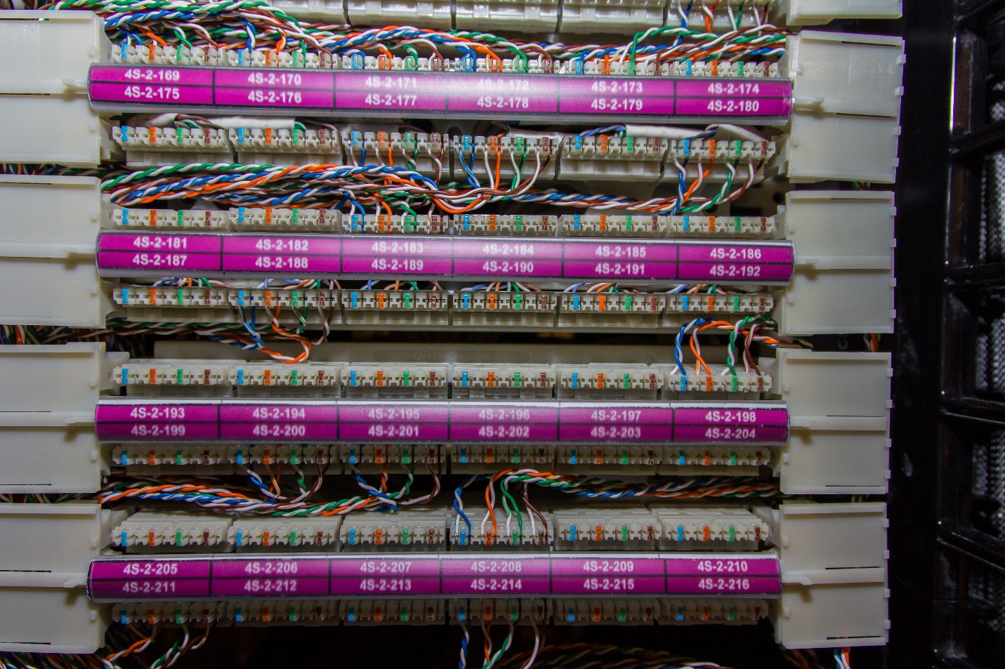
    As an aside, the station-labeling scheme employed here works as follows: {IDF}-{Panel}-{Position}. In this example, the top-left-most visible block tells us that this cable is labeled as Position 194 in the 2nd Panel of the 4th Floor South IDF. Somewhere out on the floor, in a cubicle or office or lab, will be a jack also labeled as 4S-2-194.

  • Ethernet stack

    And here a close-up view of a stack of 1RU Ethernet switches, serviced by the switch harnesses that terminate on blocks in a neighboring rack.